Designing Transistor Circuits
Designing a Transistor Circuit is first step in any electronic and electrical circuit design. A Transistor is fundamentally the most essential part in any electronic design. This is because of transistors which makes the electronic system that we see today. Any electronic system capability comes from two things- switching and amplification. This two functions are provided by transistors. For example, in analog systems, amplifiers are needed to amplify voltage, current or Power. A power amplifier driving an antenna at the front end or a power amplifier driving a loudspeakers are examples of application of transistor in analog domain. In digital domain, transistors are used as switches that makes up the various digital gates, NAND, XOR, AND, OR etc.There are two basic types of widely used transistors- BJT(Bipolar Junction Transistor) and FET(Field Effect Transistor). Each of them have prons and cons. For example, BJT have higher speed response in comparision to FET whereas FET consumes less area than BJTs.
Before designing a transistor circuit, we must know what we want to achieve with the transistor. In order words what is the application or function of the transistor in the circuit. For example, if we want to amplify voice that can be heard on a loudspeaker we can use a transistor as an power amplifier. Here the designing transistor circuit involves, knowing what the input signal(voice) voltage magnitude and frequency are, what power or voltage is required across the loudspeaker. For this it is necessary to know the resistance or impedance of the loudspeaker. Thus the initial assumption would be to know what the input and output characteristics are. Knowing this we can go to the next step for designing the transistor circuit which is selection of the transistors to fit the application. Once the transistor is chosen, the next step is the bias the transistor which is the process of maintaining a constant required output current (the collector current) as much as possible such that the amplification is invariant to temperature changes. Once we know what collector current we require we start by biasing the transistor circuit.
There are many biasing techniques for designing transistor circuits and the most popularly used in the voltage divider biasing. See the post Amplifier Design where details of how to bias a transistor is illustrated.
Circuit Schematic of Transistor Circuit Design
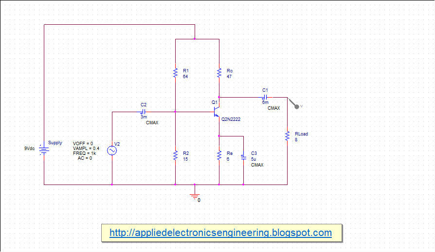
Below shows a schematic drawn in orcad capture in which 2N2222 low power transistor used as an audio amplifier to amplify 0.4V, 1kHz input signal. |
| Fig: Designing Transistor Circuits |
Example of Designing Transistor Circuits
Suppose we have a 8ohm loudspeaker and we require 2V across it to produce 0.5W power. Then below is detailed calculation used in the circuit-Vcc=IcRc+Vc
IcRc=Vcc-Vc
IcRc=9V-2V
IcRc=7V
Rc=7V/Ic
Rc=7/150mA
Rc=47ohm
Vce at 150mA= 1V
there,
Vce=Vc-Ve
Ve=Vc-Vce
Ve=2V-1V
Ve=1V
Ie=Ic=150mA
therefore,
Re=Ve/Ie
Re=1V/150mA
Re=6.66ohm
R2~6ohm
Vb=Vbe+Ve
Vb=0.6V+1V
Vb=1.6V
R1<100*Re/10
R1<100*6.66/10
R1<66.6ohm
R1~64ohm
Vcc=V1+V2
Vcc=V1+Vb
V1=Vcc-Vb
V1=9V-1.6V
V1=7.4V
R2=R1*V2/V1
R2=65*1.6/7.4
R2=12.97ohm
R2~15ohm
The output signal waveform from simulation for frequency from 20Hz to 1kHz is shown below-
 |
| Fig: All Frequency waveform at the load |
Tidak ada komentar:
Posting Komentar